
Valve performance: A key element for reliability and efficiency of reciprocating compressors in hydrogen applications
March 20, 2023
Reciprocating compressors are critical equipment in the traditional downstream sector, which relies on high volumes of pressurized hydrogen gas. Steam-methane reforming produces most of the hydrogen consumed by oil refining processes. The growing requirement for cleaner hydrogen throughout the value chain, including transportation and storage, is rapidly expanding the market for new and revamped compressors. With more compression assets to maintain, operators are focused on achieving long uptimes. Valves play an important role in the efficiency and reliability of reciprocating compressors.
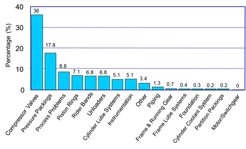
A large 1995 survey of hydrogen compressor end-users (Leonard, S M. Increase reliability of reciprocating hydrogen compressors. Hydrocarbon Processing, Jan 1996) revealed valves as the leading cause of unplanned downtime. This finding helped to spur research and development efforts which have led to significant improvements in valve technology over the past 25-plus years.
In this article, we discuss the basic functionality of reciprocating compressor valves and outline key variables that impact their performance in hydrogen applications.
Compressor Valves 101
Reciprocating compressor valves are high-speed, pressure-actuated, spring-loaded check valves. While there are many different valve styles, all employ four major components: 1) seat, 2) stopplate, 3) moving element, and 4) spring.
Figure 1 below shows a MAGNUM™ valve with the components labeled. These specialized check valves come in various shapes and sizes. However, they all perform the same function and that is to allow low-pressure gas to enter the cylinder where it is compressed and exits as a high-pressure gas.
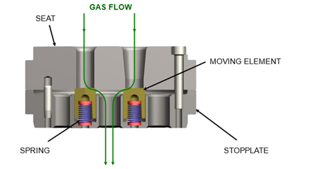 Figure 1. MAGNUM style valve
Differential pressure across the valve provides a force to push the moving element away from its closed position against the seat to its open position against the stopplate. The vertical travel distance of the moving element is defined as the valve lift. The springs provide a force to return the moving element from the stopplate back to its closed position against the seat. The valves actuate every 200 milliseconds or less (depending on compressor speed) and are subject to harsh fatigue loads.
Still, they are expected to operate efficiently and problem-free between scheduled compressor overhauls, which are typically every three years or longer. This underscores the criticality of valve design, operation, and maintenance.
Factors that Impact Valve Performance
Sealing elements and springs are the moving parts of the valve. Design engineers study them closely because they bear the brunt of the wear and tear. “How long will it last?” is the question most commonly asked about compressor valves. The answer depends on many variables, which are generally divided between design factors and operational factors.
Design factors are controlled by the valve OEM, while operational factors are determined by the compressor end-user. Designers will balance valve reliability and compressor efficiency by selecting the valve lift, spring force, and materials of construction. Computer algorithms simulate the valve dynamics using operating parameters such as pressure, temperature, molecular weight, and compressor speed. The final valve design is tailored in accordance with application guidelines.
Operational factors most often relate to gas quality, particularly whether solid contaminants or liquids exist. If dirt and debris from the gas stream enter the cylinder, then valves, piston rings, rider bands, and packings are at higher risk of increased wear and premature failures. Since liquids are virtually incompressible, valves can be overstressed when the piston tries to compress liquid entrained gas. Improper cylinder lubrication, either too much or too little, can result in sub-optimal valve dynamics. Operating the compressor at significant off-design conditions can also negatively affect the valve dynamics. Finally, poor valve repair practice can severely shorten valve life. If commercially produced hydrogen is generally considered a clean gas, then most operational factors affecting valve reliability are of lesser concern than the valve design factors.
Valve Designs
Many different valve styles have emerged over the years resulting in a wide range of moving element geometries. Virtually all have been applied in hydrogen service with varying degrees of success. The five major valve types are described below (and shown in Figure 2).
Concentric Ring Valve - Each valve assembly uses multiple rings of different sizes (diameters). Although the figure shows a valve assembly with just four rings, larger valves accommodate up to 10. Each ring has its own set of springs. To protect the spring during actuation, a small cylindrical button is located between each spring and its ring. These rings have a rectangular cross section and seal against a flat seating surface. Concentric ring valves were commonly applied in hydrogen compressors in the mid-1990s, which is when the survey was conducted.
Ported Plate Valve - The ported plate is essentially a connected set of concentric rings in a single valve element. Since valve sizes vary widely, so too do the sizes of the plate. The plate is supported by a well-balanced spring arrangement. As with the concentric rings above, the plate seals against a flat seat surface.
Poppet Valve - The poppet valve element features a mushroom-shaped head, which has a significantly larger diameter than the stem. Each return spring is housed in the stem. The springs have a higher slenderness ratio (length to mean diameter) than other valve types. The poppet head is contoured and seals against a beveled surface on the seat.
MAGNUM HAMMERHEAD™ Valve - The patented HAMMERHEAD valve uses an element with a head-to-stem diameter that is much smaller than the poppet. The return springs, which are also smaller, use non-metallic inserts. The contoured head of the element seals against an angled seating surface.
MAGNUM Valve - The MAGNUM valve uses a cylindrically shaped element, so the head diameter and stem diameter are the same. Alternatively, the MAGNUM’S bullet element can be thought of as “headless”. The relatively small return springs use the same non-metallic inserts as the HAMMREHEAD. The angled head of the element seals against a beveled surface on the seat. The MAGNUM has been the valve of choice in hydrogen compressors for nearly 25 years.
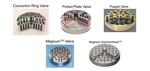 Figure 2. Different types of reciprocating compressor valves
Valve Efficiency
An efficient valve allows the compressor to deliver the highest flow rate of gas at the desired pressures by consuming the least amount of power. Valves can be thought of as an orifice with a flow area that is defined by the valve geometry. A larger orifice has less flow restriction and induces less pressure drop.
Because there is a relationship between pressure drop and power consumption, the larger the orifice (i.e., valve flow area), the smaller the power consumption. Since all gas entering the compressor must flow through the valves, minimizing the valve pressure drop promotes better compressor efficiency by minimizing power consumption of the driver.
Hydrogen compressors are commonly driven by large electric motors, and there is value in minimizing their power consumption. Maximizing valve flow area is just one of two main considerations to optimize valve efficiency. The other is valve clearance.
Most valves are positioned as close as possible to the cylinder bore. Specifically, the inlet valve stopplate and the discharge valve seat are located adjacent to the cylinder bore. Valve clearance is defined as the volume of gas contained in the flow passages of the inlet stopplate and discharge seat because these volumes communicate with the cylinder bore and therefore add to the cylinder clearance. Since higher cylinder clearance reduces compressor flow, higher valve clearance also results in less compressor flow, and therefore less compressor efficiency. Hydrogen compressors must run efficiently, so the design goal becomes one of providing valves with optimized flow area and low clearance.
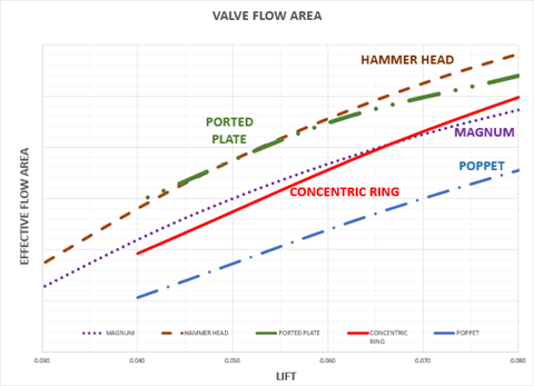 Figure 3. Lift vs Effective Flow Area of different valve types
Higher valve flow area is achieved with higher valve lift, but only up to a certain limit. The geometric characteristics of each valve type determine this limit of lift, beyond which more flow area cannot be obtained. Laboratory tests measure the flow coefficients at various lifts, allowing flow areas to be obtained for each valve type.
A graph of Lift vs Effective Flow Area comparing different valve types is shown in the figure. Since pure hydrogen is the lightest gas, with a molecular weight of 2.02, and since valve pressure drop is directly proportional to molecular weight, reasonable valve pressure drop for hydrogen applications can normally be obtained with relatively low valve flow area. Therefore, lower valve lifts are normally applied in hydrogen service. The highlighted area of the figure compares the flow areas of different valve types in the lift range of 0.030” to 0.080”.
Therefore, valve efficiency for hydrogen applications is determined by evaluating distinctions in clearance vs. flow area between the different valve types. The MAGNUM valve, with its relatively small moving element and optimized distance between elements, is specifically designed for low clearance yet has flow area equal to concentric ring valves. The concentric ring, ported plate, and HAMMERHEAD have higher valve clearance volumes. The poppet valve, with its relatively tall moving element and large gas passages, has the highest clearance volume and lowest flow area of all the valve types.
Valve Reliability
Just as valve efficiency is important for overall compressor efficiency, the same is true for valve reliability and the overall uptime of the compressor. The findings from the 1995 hydrogen compressor survey clearly illustrate this point. Several design factors influence valve reliability, such as materials of construction and geometry/configuration.
Gas compatibility, strength, impact resistance, and corrosion resistance are important variables to consider when selecting a material of construction. Materials for hydrogen service are well established. Nodular iron (also called ductile iron) is a proven seat and stopplate material for all valve types, but other grades of iron and steel can also be used.
Before the advent of non-metallic moving elements, which are used in nearly all valve types today, concentric rings and plates were made from stainless steel. However, when steel rings and plates failed in service, fragments of the broken pieces would cause secondary damage to pistons, cylinder liners, and adjacent valves.
PEEK (PolyEtherEtherKetone), a high-strength thermoplastic that does not absorb moisture, is commonly used to manufacture today’s moving elements. PEEK absorbs impact velocities much better than stainless steel, and if an element fractures, broken pieces rarely cause significant secondary damage.
A wide range of wire materials are used for springs, including chrome-silicon alloy steel and 17-7 PH stainless steel.
All of the above-mentioned materials are compatible with pure hydrogen, including hydrogen produced by alkaline electrolyzers that may contain traces of potassium hydroxide (KOH). Some hydrogen-rich mixtures may include corrosive constituents like hydrogen sulfide (H2S). In that case, NACE (National Association of Corrosion Engineers) standards for sour gas service may apply, which will alter the material selection of some components. For example, even though nodular iron is a proven seat and stopplate material in sour service, end-users may prefer the more corrosion-resistant 17-4 PH stainless steel. PEEK is inert to most gases and works well in sour service. ELGILOY® and HASTEALLOY® are among the various spring materials that meet NACE standards.
The moving elements in the valve are subjected to stresses imposed by differential pressure forces and impact forces. Differential pressure is the difference between discharge pressure and inlet pressure on each stage of compression. The moving element must be strong enough to resist the differential pressure force when it is closed against the valve seat. Its strength depends on the geometry and material of construction.
The valve element impacts the stopplate when it opens and the seat when it closes. The opening and closing impact velocities increase at increased valve lifts, higher operating pressures, and higher compressor speeds. Therefore, it is important to calculate the moving element’s impact velocities to ensure it can withstand the impact forces. Hydrogen compressors normally use valves with lower lifts, in the range of 0.030” - 0.060”. Most motor speeds are relatively low, in the range of 300 - 600 rpm. This combination bodes well for good valve reliability, even at high discharge pressures.
The ability of a moving valve element to absorb high impact velocities often determines how long it will last. Some element geometries are better suited than others to handle heavy impact loads. The nature and amount of the moving element’s contact surfaces are key. Flat contact can be problematic. Concentric rings with rectangular cross sections have flat contact surfaces. In operation, initial contact occurs at the outer edge of each ring. This relatively high point load imparts high tensile (bending) stress on the rings. The typical failure mode of a concentric ring is fracture that originated at an outer edge.
Ported plates also have a flat contact surface. If the outer diameter of the ported plate is circular, then it operates the same way as a concentric ring. The most frequent mode of ported plate failure is also fracture that initiated at an outer edge. The Siemens Energy patented polygonal ported plate geometry forces the initial impacts at an edge with higher cross-sectional area than a circular plate and is better able to absorb the impact velocities.
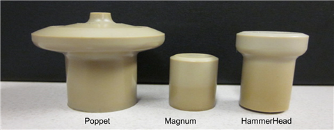 Figure 4. Valve geometry of poppet, MAGNUM and HAMMERHEAD valves
Mushroom-shaped poppet elements were among the first to use angled surface contact instead of flat contact. The stress profile on the poppet head was found to be favorable for many hydrogen applications.
However, the high head-to-stem ratio places a differential pressure limit on the poppet element, so it was not able to be applied on the final stage of some hydrogen compressors. Years later, MAGNUM and HAMMERHEAD elements were designed with optimized angled contact surfaces that more effectively disperse the impact energy and therefore withstand much higher impact velocities.
Valve Selection
Finite Element Analysis (FEA) shows minimal tensile stresses on the MAGNUM and HAMMERHEAD elements, even under high loads. It helps that they have much smaller diameters than concentric rings and plates. Valve elements with minimal tensile stresses should be robust and durable because if they cannot easily bend, they cannot easily break.
Long-term, in-house lab testing on a high-speed compressor confirmed the MAGNUM element can withstand extremes of differential pressure and discharge temperature under high impact loads. Where flat-plate geometries would fail, the MAGNUM survived. After three years of successful beta testing in over 100 compressor cylinders, with an accumulated valve run time of 250,000 hours, the MAGNUM valve was introduced to the market. Well into its third decade, the MAGNUM valve has been successfully applied in hundreds of hydrogen compressors, including many with non-Dresser-Rand nameplates.
As the hydrogen economy continues to scale up globally, compressor applications requiring much larger cylinder bores are becoming more common. Since minimizing cylinder clearance is key to achieving required compressor flow rates, these larger cylinders use fewer but larger valves. To simultaneously achieve required compressor efficiency, these larger valves must be designed to provide much higher flow areas. That unique design challenge was overcome by applying the Siemens Energy HAMMERHEAD valve. In-house flow testing shows the HAMMERHEAD provides significantly more flow area than the MAGNUM valve. To achieve high valve flow areas, the HAMMERHEAD poppet element features a slight contoured head, optimized with Computerized Fluid Dynamics (CFD) analysis. HAMMERHEAD valves were rapidly deployed and adopted in the market and are proving to be as reliable as the MAGNUM valve.
When compressor valves don’t work properly, compromised springs may be involved. The dynamics of reciprocating compressor valve springs is complicated. A full understanding has proved elusive. Conservatism in spring design is therefore useful. In addition to using a gas-compatible material, selecting wire with adequate tensile and fatigue strength for the application is important. This can be challenging if the valve element geometry and operating conditions constrain the spring design to be made from a certain material, wire diameter, outer diameter, and free length.
The motion of compressor valve elements resembles a square wave, with rapid opening and closing events. This square-wave motion can impose high spring stresses. Springs are designed to always be in compression and are therefore pre-loaded in the closed position. However, if the valve element opens with particularly high force, the initially pre-loaded spring could move beyond its final design height and hop away from the element. Such overshoot means the spring could compress to its solid height, potentially overstressing the wire.
In the field, if springs are found with adjacent flat coils, often shiny, this is the telltale sign of coil-to-coil contact. In the case of the MAGNUM valve, all springs are designed with very low solid height stresses to minimize concerns with coil-to-coil contact. Since MAGNUM and HAMMERHEAD valve assemblies are designed to use individual, identical springs, there is built-in balanced spring pressure. This contrasts with individual concentric rings, which have non-uniform spring pressure (spring force divided by ring area). Valve dynamics with such an imbalanced spring pressure can be poor, potentially resulting in some rings that close late and others that flutter (oscillate badly). Valve motion such as this can result in premature spring failures, ring failures, or both.
Operation and Maintenance
End-users who properly operate and maintain hydrogen compressors with proven, reliable valves expect them to last until the next planned unit overhaul (typically three to five years or more). The most durable valve is still a wear part and eventually must be repaired or replaced, so best practice is to stock spare parts and valve reconditioning tools at site.
Most hydrogen make-up compressors are multi-stage units with different cylinder sizes, so many different valve sizes are often encountered in a single compressor. Therefore, when concentric ring and ported plate valves are used, several ring and plate sizes would have to be stocked. These valve types also use different spring rates, which necessitates different springs to also be stocked. This can be costly and cumbersome.
By contrast, the MAGNUM valve element, made from a special blend of PEEK, is used in all valves in all stages of compression. The MAGNUM spring lineup consists of only four different spring rates and just two different spring materials. Therefore, the typical valve replacement components for an entire compressor consists of one MAGNUM element part number and only one or two spring part numbers.
If HAMMERHEADS are applied instead of MAGNUMS, the stocking situation will be the same. The HAMMERHEAD valve element would be used in all stages of compression. Since the HAMMERHEAD valve design employs the MAGNUM spring lineup, only one or two spring part numbers are used in the entire compressor. When MAGNUM or HAMMERHEAD valve repair becomes necessary, a special seat bevel reconditioning tool is available to bring the sealing surfaces back to factory specifications. The MAGNUM and HAMMERHEAD ease the logistical challenge of stocking spare valve components to the greatest extent possible.
Case Study: Extending MTBF of Hydrogen Compressors in a Refinery
A major oil refinery in the United States was experiencing a valve mean time between failure (MTBF) of 10 months on a fleet of 21 compressors that had 50 cylinders in continuous operation. This short MTBF represented the primary reason for unscheduled compressor shutdowns at the refinery. Most of the compressors are in hydrogen service and operate at discharge pressures up to 1825 psia and at motor speeds ranging from 285 rpm - 585 rpm. An annual average of 16 valve failures from 2000 - 2002 meant that a dedicated crew of mechanics changed valves every three to four weeks. This was the setting in which MAGNUM valves were beta-tested on a small compressor at the refinery for approximately two years. Upon successful testing, MAGNUM valves were installed in two of the refinery’s largest hydrogen compressors and ran flawlessly until the next planned turnaround.
Most of the remaining compressors were retrofitted with MAGNUM valves over the next three years. The annual average valve failures between 2003 - 2007 dropped from 16 to two across the same fleet of 21 units. From 2008 - 2015, the fleet expanded to 27 compressors with 70 cylinders in continuous operation, during which there was an average of just one MAGNUM valve failure per year. For a sense of scale, there are over 500 valves installed in all 27 compressors.
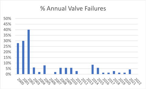 Figure 5. Substantial Reduction in Annual Valve Failures
By 2016, all compressors were outfitted with MAGNUM or HAMMERHEAD valves. The average number of valve failures from 2016 - 2022 was also just one per year. In fact, the only valve failure recorded in 2022 was not attributed to typical wear and tear, but rather to process deposits in the gas stream.
The valve MTBF increased substantially to 60 months after MAGNUM valves became the refinery standard -- representing a six-fold improvement that continues to be maintained. Figure 5 shows the sharp reduction in valve failures after MAGNUMS were introduced 20 years ago. The rapid and sustained improvement in MTBF means the compressor valves are no longer the primary reason for unscheduled shutdowns at the refinery.
To quote a refinery reliability engineer: “The original goal was to be able to run our compressors a minimum of 5-year intervals without any maintenance requiring a shutdown. Before converting valves to MAGNUM valves, we couldn’t even dream of approaching that goal. Since utilizing MAGNUM valves our MTBF has steadily increased to over 5 years. This was a joint effort between us and the manufacture/designer which required a significant amount of work in a short period of time to reach and exceed this goal. This increase in valve life has translated to increased piston and rider ring life.
Previously when valves started to fail there would be a rapid increase in local temperature due to the valve designs. This localized heating is most likely the cause of rider and piston ring degradation. Operations will always continue running until the bulk discharge temperature shutdown occurs. A potential scenario would be a failed or failing head end discharge valve on a Friday that would result in a wrist pin failure by Monday. The MAGNUM valve’s ability to continue running while partially damaged (we call “limpability”) is what prevents these failure mechanisms from happening.
Prior to this effort we had significant numbers of unplanned “costly” shutdowns. Today we typically run turn around to turn around where we perform our overhauls on a preventive maintenance basis.
We see machines running 7-8 years and our goal is moving forward from 5 years. Someday we may achieve 10 years without a shutdown as a common occurrence on a large cylinder population.”
Conclusion
For decades, reciprocating compressors have played a critical role in delivering high-pressure hydrogen in refinery applications. In recent years, their range of uses has expanded to include electrolysis plants, hydrogen liquefaction plants, and hydrogen pipelines. While compression requirements in these different facilities vary, uptime and efficiency remain key. Valve design is critical in this regard and is a key area of focus for end-users and operators. Proper valve application avoids revenue losses associated with unplanned downtime.
MAGAZINE
NEWSLETTER
CONNECT WITH THE TEAM