
The evolution of compressors for making iron & steel
July 08, 2024
The Cornerstones of Compression series has highlighted many significant products over more than 160 years of continuous progress. This is the first of a series of corollary articles that look back at the industries that drove the invention and technological evolution of compressors that supported their growth and development.
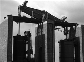 Re-erected 1817 Boulton and Watt walking beam steam cylinder driven air blowing cylinder.
The history of compressors can be traced back thousands of years to when early civilizations discovered the power of the human lung. With its ability to exhale oxygen, the lung made it easier to build fires for cooking and keeping warm. Sometime around 5000 B.C., the science of metallurgy was born as tools, weapons and religious idols were fashioned from metal. Among metalsmiths, it became apparent that more air for hotter fires was needed to turn liquidized minerals like copper and gold into hard metals.
The earliest man-made air device was the blowpipe, which metallurgists in Egypt used in the production of precious metals found in ancient tombs. But, in light of the demands brought on by metal production, the limitations of the human lung became readily apparent. At its healthiest, the human lung is only capable of producing a fraction of the air pressure needed for melting metal. Furthermore, lungs proved to be an unsuitable source for fire sustenance due to the carbon dioxide content in the air that humans exhale. Clearly, something more powerful and elaborate was needed for air production.
Primitive Human-Powered Bellows
The very first development of mechanical devices for compressing air was for blowing air into blast furnaces for making iron and steel. The first primitive smelters appeared in China in the first century AD using human powered “bellows” made of animal bladders to force air into the furnaces. Consisting of a flexible bag, the device made compressed air production possible. Later, accordion-like bellows were developed, which sucked air in through one side while extended, and then pushed the air out through the other end when the handles were squeezed together. Eventually, animal or human-powered wheels appeared with crude crank and connecting rod contraptions that created a reciprocating motion necessary for pushing on the bellows.
Water Powered Trompe
In the eighth century, a small forge in Catalonia in northeastern Spain discovered the benefits of using a nozzle known as a tuyere to blow air from a manually operated bellows into layers of charcoal and iron ore in a hearth. This greatly increased the amount of iron produced, and it was scaled up over the next 200 years throughout Europe. Using a water column air aspirator known as a trompe, the air pressure was increased to about 1.5 psig (0.1 bar), which accelerated the smelting process and further increased production.
Water Wheel Powered Bellows
While small refinements were made here and there, the basic design of the bellows remained unchanged for a staggering three millennia. It wasn’t until the 1600s when inventors began designing ways to rig the blowing machine to a water wheel. The continuous air flow provided by this mechanism led to the smelters being referred to as blast furnaces, and from that time forward, technology started advancing much more rapidly. It is worth noting, of course, that bellows have not disappeared — they can still be found by fireplaces, in accordions, musical pump organs and other devices.
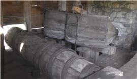 Replica of bellows at the first North American blast furnace at Saugas, Massachusetts, c.1645.
The first operating North American blast furnace was at Saugus, Massachusetts in 1645. Its two bellows, shown in the reconstruction of the original version in Fig. 1, were driven in reciprocating fashion by a cam shaft connected to an overshoot waterwheel. The bellows were deflated by the cams on the main shaft and were inflated by counterweights consisting of wooden boxes filled with stones and mounted on two moving beams that extended through holes in the casting house roof.
Blowing Tubs
The development of blast furnaces brought about the need for a more powerful form of compressed air. In 1650, German physicist Otto Von Guericke designed a vacuum pump that could pull air through tiny chambers and leave compartments air free. More than a century later, John Smeaton conceived an even more influential idea. He was generally believed to be the world’s first professional engineer, and in 1762, he designed a new type of blowing device driven by water wheels. An eccentric crank on a waterwheel had a reciprocating piston rod and blowing tub on each side. The piston inside the tub was fitted with leather to form a seal. The wooden blowing tubs were either square or round and held together with external steel hoops. As one piston was ascending to compress air in one tub, the other piston was descending in the other tub. At the top of each tub was an outlet pipe connected to a common mixing box that was always under pressure. The mixing box fed compressed air to an air duct or blast main which led to the furnace tuyeres. A typical blowing tub was 72 in. (1829 mm) in diameter and 72 in. (1829 mm) tall and produced 2 psig (0.14 bar) of pressure.
Steam Power
In 1769, a steam engine was first used as a driver for blowing tubs. This was followed in 1776 by English inventor John Wilkinson, who created a high-powered blasting unit that would serve as a precursor to the compressor machines of today.
The development of large reciprocating steam engine blowing compressors that provided greater volumes of blast air at a significantly higher pressure was a major step in the evolution of high production blast furnaces. Early engines were of the walking beam type. As shown in Fig. 2, the re-erected 1817 Boulton and Watt blowing engine’s steam cylinder piston rod was connected to one end of a gallows beam. The blowing cylinder’s piston rod was connected to the other end of the beam, and each stroke of the steam cylinder provided a corresponding stroke of the blowing cylinder.
As industrialization swept the U.S in the 1800s, blast furnaces became increasingly common, growing in number and size. Several companies began producing blowing engine-compressors. For example, in the 1890s, Edward P. Allis & Company was building vertical 60 in. (1524 mm) stroke machines with 42 in. (1067 mm) diameter steam cylinders and 84 in. (2134 mm) diameter air cylinders, as shown in Fig. 3. Further evolution of these huge machines will be discussed in the next issue.
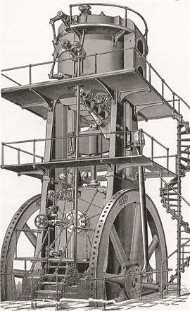 In the 1890s, Edward P. Allis & Company was building vertical 60 in. (1524 mm) stroke engine-compressors with 42 in. (1067 mm) diameter steam cylinders and 84 in. (2134 mm) diameter air cylinders.
MAGAZINE
NEWSLETTER
CONNECT WITH THE TEAM