

Power towers: large luffing cranes for wind turbine work

October 22, 2024
New tower crane concepts for wind turbine installation. Part one of an epic series written by ICST special correspondent and global tower crane authority Heinz-Gert Kessel
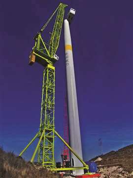 Jinli Heavy Industries’ JLD1700 installing a 2 MW turbine standing at 95 metres. Photo: H-G Kessel
At the beginning of tower crane application for wind farm projects, this breed of crane was tried as an alternative to large mobile lattice boom cranes, on sites where space and access were restricted, writes Heinz-Gert Kessel.
The focus was to have high capacity at a short outreach. Converting a standard heavy lift tower crane into a wind turbine installation crane only needed a limited number of design changes. A good example is the Liebherr 630 EC-H70 of construction company Max Bögel in Germany. It has a strengthened short jib and a special trolley for multiple falls of rope to cope with the requested 70 tonne load, up from the standard version’s 50 tonnes capacity.
In China the FZQ series of 130 tonne high capacity luffing jib tower cranes, originally built for power plant boiler house construction, were repurposed for wind turbine installation. For both concepts one of the main design aspects was to minimise special features to redesign the crane quickly for general construction projects outside the wind turbine installation industry.
Already in its first prototype application, however, this approach highlighted the main disadvantage. The crane was originally designed for a project duration of at least 3 to 5 months. Mobilisation and demobilisation times could never compete economically with fast-rigging mobile cranes on wind turbine job sites that generally last just a week.
Adaptation of the standard tower crane concept for easier transport and faster rigging became more and more an essential feature when evaluating the viability of wind turbine tower crane concepts. A first breakthrough at manufacturer Liebherr was a flat top crane design instead of the standard saddle jib with tower head and pendants. This reduced the installation time of the crane upper.
Different luffer
Krøll in Denmark developed an alternative luffing jib design where the time-consuming reeving of the luffing rope was no longer needed. The pre-reeved bridle could rest on the A-frame where also the luffing winch was attached. A luffer allows boom outreach to be transformed into lifting height. It is a brilliant and fast solution to gain extra under hook height.
Additional under hook height was realised by Krøll for the first time when introducing the distinctive boom nose jib tip section to provide more clearance from the load at the maximum under hook height.
The above two design concepts were later integrated in all subsequently released Chinese wind turbine tower cranes. These included similar looking cranes from Jinli Heavy Industries, XCMG, Yongmao, Sany and Zoomlion.
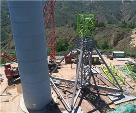 Zoomlion LW2340-180 undercarriage on a narrow mountain wind power project. Photo: H-G Kessel
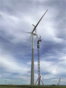 Yongmao STF3080 with a 200 tonne capacity to an under hook height of 200 metres. This crane incorporates common design features pioneered by Krøll. Photo: H-G Kessel
Depending on the dimensions of the mast system, a common maximum free standing under hook height for top slewing luffing jib wind turbine cranes seems to be 180 to 200 metres. Load capacity is usually between 180 and 200 tonnes.
Above 140 tonnes lifting capacity the crane’s components tend to be all oversize for transport. An advantage of luffers over conventional tower cranes is that fewer mast sections are needed to achieve the required hub lifting height. It also saves installation time for jacking the crane.
Free-standing tower cranes generally provide the most flexibility for wind turbine tower design. As wind turbines get taller, however, more costly and stronger mast sections must be used. In many cases this means a longer rigging time and more abnormal transport loads, all again adding to the mobilisation cost.
Still a major disadvantage exists concerning the tower crane base when comparing it to a large mobile lattice boom crane. Mobile cranes can generally be moved from one turbine to the next at least partially rigged. A tower crane must be completely dismantled, including its large and heavy base.
To help speed up the process two tower crane bases can be applied on wind projects. While one is in use the second one can be reinstalled at the next job site. Such a crane concept will clearly not be as economical as it should be. More recently, special mobile tower crane bases have been designed or are in development. The success of such designs under real site conditions will depend on the size of the crane and the preferred technical solution.
Ways of moving
In Japan two tower crane mobilisation concepts have been prototyped. They incorporate wheeled self propelled modular transporter (SPMT) for relocating turbine tower cranes. Shimizu Corporation completed its S-movable Tower crane. It is a large 1,800 tonne-metre class mobile tower crane for onshore wind turbine installation in the 5 to 7 megawatt class.
Designed to be earthquake proof the new crane lifts 145 tonnes at 12.5 metres radius to a height of 152 metres. That makes it the largest and highest self-supporting tower crane in Japan. It is a joint development between SC Machinery and IHI Transport Machinery.
Field testing of the crane concept is underway and the companies are test relocating the crane using SPMT in the Shingu District of Japan, on the Kure city shipyard side. The complete upper crane remains installed so the crane only climbs down into its lowest position and the diagonal bracings and the legs of the base are disconnected. It is then ready to quickly move to the next site. The relocation cycle is shortened by about six days, according to Shimizu Corporation.
Cranes using a traditional Japanese type of cylindrical tower which absorbs wind pressure and at the same time allows climbing the tower system through a compact slewing ring support, are mounted on a specially developed, four leg, cross-shaped pedestal.
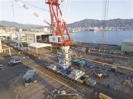
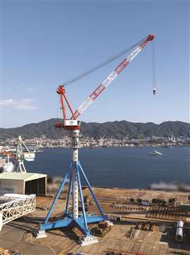 The IHI S-Movable Towercrane with legs installed. Photo: H-G Kessel
Safer climbing
The Japanese way of inserting tower sections through the slewing ring offers a real safety advantage for climbing in harsh weather. It also allows the crane to be jacked on the same size of tower system at a very low level. The 97.50 metre high tower system is made up of 14 tower sections. Thanks to the special Japanese way of climbing, a maximum of three tower sections can be inserted in one climbing process, into the climbing device, reducing the number of tower connections to be made during operation on a windfarm.
To reach the 97.50 metre free standing height, on a 2.45 metre square metre (optimised for transport) base, some diagonal bracings had to be added to the tower, installed by the tower crane itself. Connecting this tubular structure to the central tower is done by a patented fast installation device served from inside the tower and therewith under safe access conditions.
In contrast to European and Chinese wind turbine installation tower crane designs, these very long mast stays greatly suppress mast deflection on a free-standing crane. Unlike standard construction cranes the number of jacking steps alongside the tower to raise the crane have been reduced by developing a new fast hydraulic jacking device.
When moving the crane, the centre part of the cross-base is on SPMT with a special mount. After disconnecting the outer parts of the legs to reduce the transport width of the crane, the massive outrigger pads are mounted onto the SPMT unit as ballast to compensate the point of gravity of the crane.
In addition, when relocating the complete crane upper, including its 55.55 metre jib and all ropes being kept reeved, the machinery deck will be fastened with special load securing ropes to the SPMT platform. While the crane will generally be operated from the crane operator’s spacious and comfortable cabin, it can also be operated remotely from the ground or from up the wind turbine.
In the long term IHI forecasts increasing demand for such high-capacity tower cranes. In Japan, in contrast to Europe and China, more moderate wind turbines with 100 to 120 metre hub height in the 4 to 5 megawatt size are more common. Experience in Europe with tower cranes for turbine erection has already shown the required capacity of the cranes and their lifting height quickly increases, to the point where cranes could not be too big.
 The complete IHI crane upper ready for transport on SPMT. Photo: H-G Kessel
MAGAZINE
NEWSLETTER


CONNECT WITH THE TEAM