Trash Compactors And Old TVs
27 November 2017
This article was originally published in the October issue of COMPRESSORtech2. We only publish a fraction of our magazine content online, so for more great content, get every issue in your inbox/mailbox and access to our digital archives with a free subscription.
Charlie Irwin is just your average American who loves motorcycles, has filed five patents, developed paint coatings that were used on the lunar lander and rover, writes his own control software and is fortunate not to have been arrested for building and launching his own rockets from his backyard in Houston, Texas, during the space-race era. He, with the help of packager Bob Clark, owner of Clark Compression, is also the man trying to make the use of hydraulic compressors the go-to for gas lift and well-bore treatment.
The need
Though he had been in the gas compression industry for decades, beginning as a field serviceman with no training and learning the trade through books, Irwin’s foray into hydraulic compression didn’t begin until the late 1990s. In 1998, he took his “dream job” to be a field operator in Orla, Texas, as he took over as president of LenOp.
“At the time, Orla had a population of three, and I made it four,” Irwin said.
The job turned out to be a nightmare, but not because Orla is a modern-day ghost town. Irwin was doing gas lifting, but wet gas was damaging compressors.
“I decided I was going to solve the problem,” Irwin said. “I started looking for compressor frames to work with, but I could not buy anything new or used. CSI … and especially Hanover, were buying everything back then. Nothing was available.”
Irwin had to search for something besides high-speed compressors. He remembered seeing a Universal Compression hydraulic compressor back in 1981 and tried to buy one, but they had stopped making them, plus, they had significant problems. Weatherford had also made hydraulic compressors, but they didn’t work for Irwin’s purposes, though, some did work as intensifiers.
With nothing readily available, Irwin decided he would just build his own compressor. He had experience packaging and writing the sizing programs for natural gas compressors when he worked for Energy Industries in the 1990s, and had built separators for Surface Equipment. Irwin had the necessary knowledge.
“Designing really wasn’t the issue; it was more about what was available to work with,” Irwin said. However, he didn’t instantly find success. Irwin’s first design was so obviously going to fail, that he never even built it. If he was going to succeed with a hydraulic compressor design, it was going to have to be significantly different than its predecessors in the industry. So Irwin began to think outside tradition.

Curious inspiration
“I used to work in the paint industry, and outside they had a big trash compactor. I knew how it worked and decided to try that technique,” Irwin said.
The trash compactor technique was the first major difference from other compressors because it uses variable stroke lengths. Previous hydraulic compressor designs pushed the piston full-stroke every time, which became a problem when any fluid got in the cylinder. The machine would stall and shut down until someone came and fixed it. Even without a fluid problem, if the gas pressure was too high, the compressor would run out of power before it could reach the end of the stroke.
But with a trash compactor, it didn’t matter how much trash was in the bin; or, in this case, how much gas, fluid or both got into the cylinder. The stroke wasn’t controlled by the gas pressure in the cylinder or a set distance — it was controlled by the hydraulic pressure controlling the ram. That meant that as pressure inside the cylinder increased, regardless of the reason, it created more hydraulic pressure needed to push the piston. Once that hydraulic pressure reached a set point, the stroke would stop pushing forward and return with- out the need to travel the full length of the cylinder.
“In the high-speed compressor industry we always dreamed of a rubber cylinder that could change size easily,” Irwin said. “And all of the sudden I had one that I could change the stroke on. And it did it by itself.”
Having the stroke controlled by hydraulic pressure and not gas pressure or distance was a breakthrough in making Irwin’s compressor idea work, but there was still another, perhaps bigger, problem — automated control.
“When you have a liquid pushing a gas, the gas is nice and spongy, but the liquid is very turbulent inside the hydraulic cylinder,” Irwin said. “The piston moves in tiny little jerks all the time, and this wreaks havoc on any kind of controls. All of the modern (sensors) are polling in many microsecond intervals, and all of your current sensors avail- able cannot stand all the millions of cycles of the piston actually moving in tiny jerking motions. We tried PLCs and every type of electronic and mechanical relay for control. The best we could do was about three days of run time. And a lot of times it was down to five minutes. That was the big hurdle. We could get the mechanical function to work, but the controls would get destroyed.”
Once again, it would be outside-the-box thinking using knowledge of a technology that has been obsolete for decades to make his compressor controls work. According to Irwin, the secret sauce to making hydraulic compression has something to do with old TVs.
“I grew up in the ’50s and ’60s. Radio and TV technology was still tube-type back then, and was just starting to move into the transistor era. I had a cousin who had a radio and television repair shop. And for years I went over to his shop and watched him work on stuff, and he taught me all about it and let me have stuff to work on. And yes, I got zapped a few times. He didn’t tell me about those capacitor things; I had to learn about that myself. … I got to where I could fix TVs. I was 13-years-old repairing televisions.
“So after a long time of not finding anyone who could solve my (control) problem, I started looking at a lot of the chips that were available. And I realized I could use some old (TV) technology techniques to lie to the chips. That allowed me to develop a control board that works beautifully with this technology and has no problems with the pulsing action. It’s a little bitty module and it controls a set of bigger heavy-duty relays.”
Exactly how the module works, Irwin and Clark will not say. However, it’s not likely there are too many interested parties who could figure it out.
“There aren’t too many old people like me left alive out there who understood the old technology,” Irwin said.
With the control module in place, Irwin and company were ready to get their compressors to work.

Surprise benefits
While the trash-compactor style of compression and Irwin’s unique control module are the key components to making hydraulic compression work, the compressors themselves also comprise some novel features.
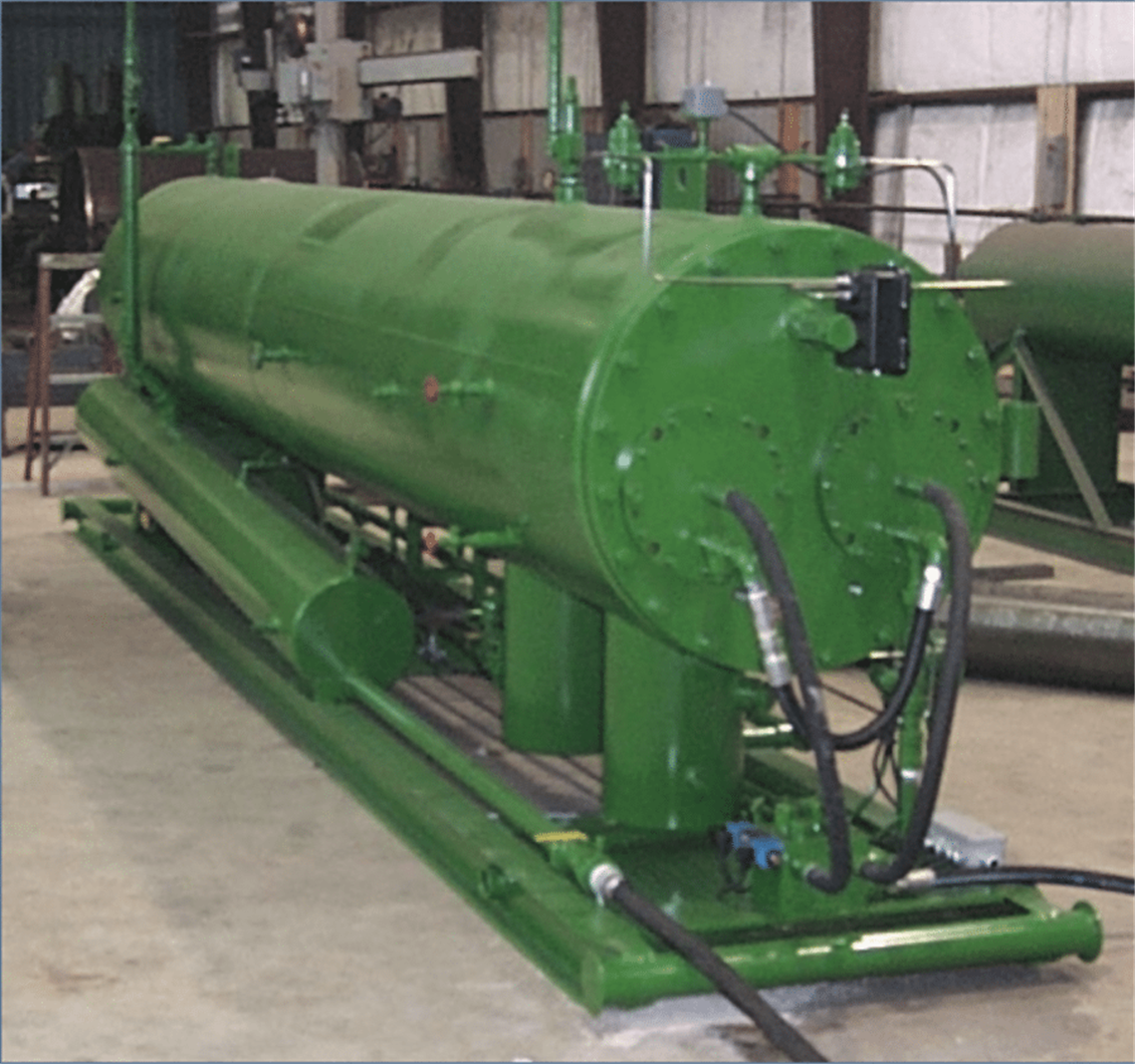
The first generation compressor, a “backwash production unit” (BPU), lovingly dubbed “the green machine,” was built in 2001 (Figure 1). This prototype, as well as all of Irwin’s designs, are manufactured by Bowers Equipment in Houston. Patents are held by BI-Comp LLC (Bowers/Irwin Compression).
The two-stage design comprised two long compression cylinders inside one large separator unit. The idea behind the green machine is that the oil and water coming into the separator from the well would act as a coolant for the internal compression cylinders. The heat from compression would also help stimulate the oil/water separation (Figure 2).
A heater treater, separator and compressor were now all in one machine on one fairly portable skid.
During the first field test of the green machine, a few problems arose, but more benefits were discovered. To test the compressor, Irwin and two partners bought an Expro Americas oil well in Buffalo, Texas, that had been dormant since 1996 with the plunger still left in the well. Before being shut in, the well had produced one to two barrels per day, but with the well fluid containing paraffin and low wellhead pressure, the plunger would routinely become stuck. The well was set to be plugged and abandoned.
In 2003, Irwin’s team took their prototype to the well, fired it up, and it broke immediately.
“I had forgot to anticipate thermal expansion inside the hydraulic cylinders,” Irwin said. “I thought the fluids would take care of the temperatures and everything would heat up at the same rate. It didn’t.”
The problem was solved by making nearly all the components free-floating. The cylinders, pistons and rods were all
loose inside the large cylinder. Nothing was rigidly attached other than the flange for the hydraulic oil to enter and the flange for the gas to discharge.
“That was a really unique part (of the design),” Irwin said. “It took the patent office a couple of years to understand it and give me a patent on it. It took their engineering group a long time to see how it could be functional, but by that time we already had them out in the field and running.”
With the new BPU prototype, a 36-hour test was conducted in which the well was stimulated. The result was the production of 42 barrels of oil.
Irwin’s idea, which was originally intended as a solution for gas lifting, worked, but there were benefits associated with the long stroke and large gas pulses he had not anticipated.
“(The pulse into the bottom of the well) creates a wave back into the formation and it moves stuff around,” Irwin said. “So the permeability — which is getting blocked by the fines and the paraffin and asphaltines, as they are always moving toward the well-bore — that stuff gets moved around and cleared up. What we also didn’t know was going on is that this wet gas is acting as a solvent to clean up the well bore. It would be like using barsol or gasoline to scrub the tubulars down. And with the gas being hot, it was also holding water that was salt-free, even though salt-water came up out of the well. So now you have hot water vapor going into the well that is being absorbed by the salts.”
Essentially, the BPU was stimulating and cleaning the well and formation at the same time. It was complete well treatment. But Irwin’s packager, Bob Clark, wasn’t completely satisfied. Although more than 20 BPUs have been built and sold, they are large, heavy and not very portable. Clark asked for a portable compressor that could be taken from well to well for treatment.
No mullets allowed
In 2006, Irwin designed his second-generation compressor, the Multistage Multiphase Unitized Linear Liquid Entrained-Gas Transfer compressor, or the MMULLET.” Not wanting the equipment to share its name with an outdated haircut or a fish, Clark renamed the MMULLET as simply “hydraulic gas compressor” (HGC) (Figure 3).

The HGC is a portable, two-stage machine with the compression cylinders facing back-to-back inside one long cylinder as opposed to adjacent positioning inside a large separator cylinder. Stage one has a stroke of 80 in. (2032 mm) and stage two has a stroke length of 20 in. (508 mm); both stages use 10 in. (254 mm) pistons, with stage one being pushed by a 3.25 in. (82.55 mm) ram and stage two pushed by a 6 in. (152.4 mm) ram.
When gas pressures allow the machine to run full-stroke distances, the machine runs at about 10 rpm. When gas pressures inside the cylinder are high, increasing the hydraulic pressure needed to push the piston, the machine will run shorter, more frequent strokes. It is always self-adjusting for maximum efficiency.
The HGC runs with an inlet pressure of around 50 psig (3.5 barg) maximum operating gas discharge pressure of about 1100 psig (76 barg). According to Irwin, such a jump in pressure in only two stages would not work in high-speed compression. But the slow strokes, low rpm and Ryton rings allow the hydraulic compressors to operate with a consistent temperature of up to 450°F (232°C) trouble-free.
Irwin’s third-model compressor is called the heat-exchange compressor (HEC). It was designed with gas flooding in mind and called for higher temperatures and pressures, which meant longer strokes than the HGC could provide. While the HGC was very portable, its stroke was limited by having both hydraulic cylinders back-to-back. In order to get longer strokes, Irwin essentially took the adjacent cylinders inside the BPU out of the separator (Figure 4). The HEC is available as a three-stage design with a discharge pressure of 3000 psig (207 barg).

“It’s not quite as portable as the HGC, so we gave up something there,” Irwin said. “But in return, we gained the ability to go to much higher ratios and higher capacities. “We also don’t want to cycle this thing too fast, because then we lose the effect of our pulse. It’s like patting your hand in a bathtub full of water. You can pat your hand a lot and get little waves, but that’s not what we want. We want big waves. The slower you go and bigger you go, the bigger wave you have and the better it affects the formation.”
To maximize the pulsing effect even more, Irwin reluctantly designed yet another hydraulic compressor.
“(The fourth-generation compressor) is something that I did not want to build,” Irwin said. “I felt it was falling into the same trap that other hydraulic compressors did. I really thought it was going to have some issues that were going to be safety concerns. But I was wrong. I put safeties inside of it to protect myself, and they did exactly what they were supposed to do and broke immediately. But then we realized that there is no real problem.”
The fourth-generation compressor is a single-stage, double-acting compressor that uses inlet gas pressure to assist the hydraulics in moving the pistons. It is intended for compressed natural gas, and is able to tolerate high pressures and even phase-change in the cylinder.

The pistons are each at the end of a single rod (Figure 5). The inlet gas coming into one cylinder helps to push the pis- ton that is compressing on the opposite end. This allows the compressor to do more work because the hydraulic pressure is lower relative to the gas it is compressing due to the gas assist, which means higher discharge pressures and very high volumetric flow during a pulse.
For example, the average amount of total flow each day might only be 700 MCFD (19,800 m3/d), but during a pulse, it is the equivalent of a machine with a flow rate of 2.6 MMCFD (73,600 m3/d).
“The message is our pressure pulsing effect,” Clark said. “We call it the ‘elastic wave.’ Oil companies want to keep everything in the formation up and moving in solution; they don’t want it to screen out.”
According to Irwin and Clark, this message is being heard loud-and-clear in Colombia, Venezuela and Mexico, and interest is growing in the United States as well. And, as important as interest is, Irwin and Clark are in a viable position to handle the growth.
“We are able to work with distributors today who have the financial backing to go out and support the equipment.”
STAY CONNECTED

Receive the information you need when you need it through our world-leading magazines, newsletters and daily briefings.
POWER SOURCING GUIDE
The trusted reference and buyer’s guide for 83 years
The original “desktop search engine,” guiding nearly 10,000 users in more than 90 countries it is the primary reference for specifications and details on all the components that go into engine systems.
Visit Now
CONNECT WITH THE TEAM